double densed uncounthest hour of allbleakest age with a bad of wind and a barrel of rain
double densed uncounthest hour of allbleakest age with a bad of wind and a barrel of rain is an in-progress piece for resonators and brass. I’m keeping a composition log here as I work on it.
As of March 2025, I’m writing about other things here too.
Thursday July 9th
I got curious about the kernel errors I see on boot (usually!)
complaining GET_CABLE_PROPERTY failed from the
ucsi_acpi module – and lo, this is actually a long-tracked
issue that explains the frustrating behavior of the framework mainboard
embedded in my instrument. The framework firmware fails to report its
settings to the kernel and this causes device enumeration to fail
(sometimes?) – the result for me is that I have to remove the HDMI
module from the framework whenever I turn my instrument on, then wait
until it boots, and then reboot (blindly via a bluetooth keyboard)
inserting the module again after boot in order to get the screen to
work. Inserting the module after a cold boot seems to never work, but
rebooting while powered does seem to work consistently. It’s very
annoying! This and the cooling issues have been making me think maybe
I’ll just put the mainboard back into a laptop shell and put it on the
floor below the instrument instead. If I can connect the main instrument
to the laptop with a single cable that’d be fine, docking it to the
instrument instead. That’s probably still the direction I’ll end up
going, especially given this issue is still open and unfixed!
ucsi_acpi USBC000:00: unknown error 0
Saturday July 4th
Computer Music Journal has been a year or more behind on their publishing schedule since the pandemic. They just published the Winter 2024 issue recently, it’s been kind of confusing to be a subscriber. They must have a huge backlog?
This morning I noticed there is a new article on their MIT press page from Barry Traux on microsound composition, dated June 10th 2026! I’m so excited to read this – his articles on live granular synthesis and microsound from the 80s and 90s have been really inspiring, and he’s one of my favorite computer musicians period. But the publication situation is weird. I can’t figure out why it’s only available as a $22 PDF download to subscribers.
I’m happy to support the computer music journal, it’s been an incredible resource for me since I started reading it as a student and I usually find something inspiring or interesting in every issue, I don’t really understand what has been going on recently with the publication schedule though, and this side-channel Barry Traux paper (which, yes, certainly I’m going spend the $22 and print it myself because it’s Barry Traux on microsound in 2026 for crying out loud!) just makes it all the more confusing.
Update: the PDF is watermarked uncorrected proof and when I went to check my subscription I saw this note:
Starting with volume 49, Computer Music Journal will be an online-only journal with articles made available online as they are ready.
I realize now that I skipped the about this issue section in the Winter 2024 issue. Sure enough they announced they’re moving to a new online-only continuous publication model. They’re only publishing a new volume once enough articles have been accumulated. There isn’t much explanation as to why, but I suppose I can guess the way the culture (in a broad sense, whatever that means) seems to be skewing toward having machines read and write for us. Whatever the reason, I’m bummed there will be no more print edition after 50 years of publication.
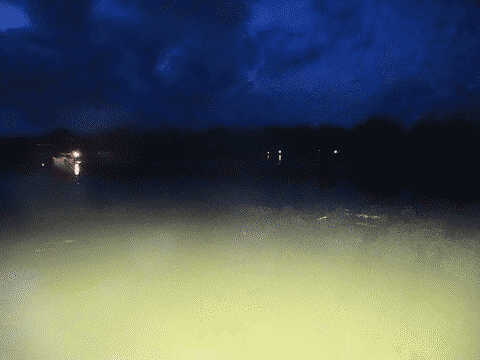
Well fireworks are fireworks, it was nice to sit by the river tonight and hear the sounds echo across the bluffs.


Friday July 3rd
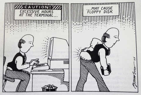
You bet.
(From UNIX System V Primer by Mitchell Waite, Stephen Prata and Donald Martin – which is also riddled with typos, incorrect & sometimes offensive examples… But also it has lots of fun cartoons by Bob Johnson like the one pictured above!)
Wednesday July 1st
This is an idle thought, but for once I guess I’ll write it down.
I’m working (slowly, it’s a low-ish priority free time project) on a backend for luvsound which I’d like to eventually open source for other indies to use… the project so far is all go + sqlite.
This has been fine. I like go. It’s portable, relatively simple and easy to deploy.
SQLite3 is great. It’s extremely portable and given its age and stability I feel like the time I have invested in learning about it is well spent.
When I transitioned pippi from python 2 to python 3 I decided to move all of the C backend into cython, and then regretted that decision since it makes it basically impossible to embed anywhere outside of python. Since then I’ve mostly ported pippi back into a C library, which has already been useful in microcontrollers and other environments.
I’d like that kind of portability for the work I’m putting into the luvsound backend, too. I realized tonight that it would be worth exploring developing each major feature as its own module (download codes, large file uploads, etc) which could persist its state in sqlite and express its behavior in C.
There would be some additional work in developing interfaces for each environment it could be supported in, but I love the idea of maintaining the core C libraries and some example interfaces in python and other environments I end up using while keeping it all portable enough to allow potential contributions of other target environments.
Log June 2026
Log May 2026
Log April 2026
Log March 2026
Log February 2026
Log January 2026
Log December 2025
Log November 2025
Log October 2025
Log September 2025 and earlier